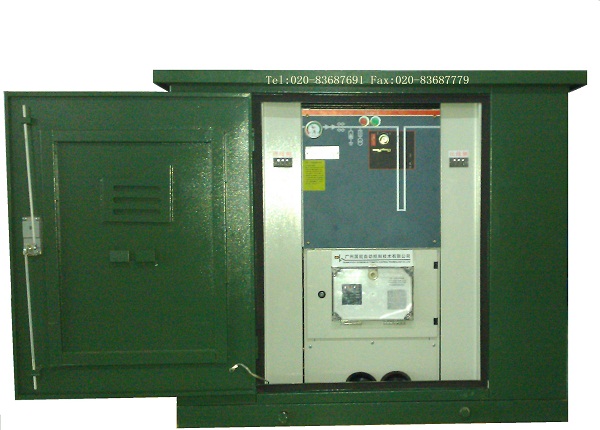
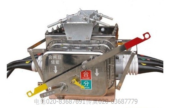
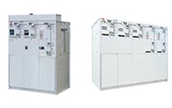
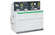
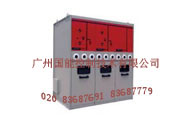
看门狗分界全绝缘全密封六氟化硫开关柜12/24/35kV/38kV/40.5kV开闭所
可配置手机app测控/智能短信控制/无线控制分合/远距离遥控分合/国能控制/安全控制/
GPRS/101/104/后台智能控制/智能分界开关箱/分支箱
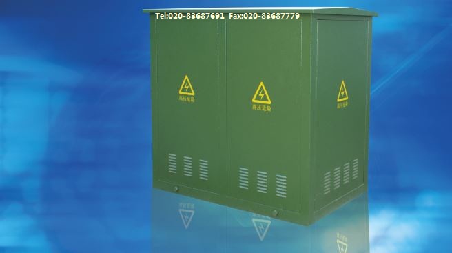
DTU/FTU/RTU测控智能开闭所/用户分界落地箱式开关柜
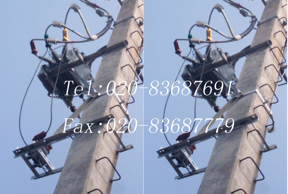
配网看门狗分界开关在10kV 24kV 35kV 38kV线路上的应用可大大减少无故障线路的连带性事故停电、缩小故障停电范围、缩短用户停电时间,从而提高用户的供电可靠性。
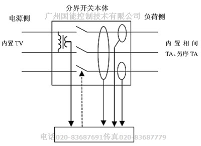
分界断路器/负荷开关是将断路器/负荷开关和分界保护测控装置,以及通讯模块融为一体的装置,可随配电网络配置、体积小、投资少,它的应用对提高配电网的安全可靠性,保证电网的安全运行具有重要意义。
我公司的分界开关其主要功能:运行中自动隔离用户侧相间短路故障、自动切除用户侧接地故障,并可用于操作拉合负荷电流。
分界负荷开关带有一套内置电压互感器、一套内置电流互感器;有CPU内部处理器和通讯模块;故障跳闸时带有电压判断和故障记忆;具备跳闸闭锁功能。
分界负荷开关适用于10 kV 24kV 35kV 38kV 中性点不接地、经消弧线圈接地或经低电阻接地系统的配电线路与用户(含临时用户)的分界。
2.2 主要作用
2.2.1 自动切除单相接地故障
当用户支线发生单相接地故障时,分界开关自动分闸,甩掉故障支线,保证变电站及馈线上的其它分支用户安全运行。
2.2.2 自动隔离相间短路故障
当用户支线发生相间短路故障时,分界负荷开关在变电站出线保护跳闸后,立即分闸甩掉故障线路。变电站出线开关重合后,故障线路被隔离,使馈线上的其它分支用户迅速恢复供电。
2.2.3 快速定位故障点
用户支线故障造成分界开关动作后,仅责任用户停电,并可主动上报故障信息,使电力公司能迅速明确事故点,及时进行现场处理,使故障线路尽早恢复供电。
2.2.4 监控用户负荷
分界负荷开关可将检测数据传送电力管理中心,实现对远方负荷的实时监控。
2.3 分界负荷开关的故障处理方式
分界负荷开关的故障处理方式见表2。
|
|
系统接地方式
|
故障点保护处理
|
|
单相接地故障
|
中性点不接地系统用户界内
|
判定为永久接地后立即跳闸
|
|
中性点经消弧线圈接地用户界内
|
|
中性点经小电阻接地用户界内
|
先于变电站保护动作跳闸
|
|
中性点不接地系统用户界外
|
不动作
|
|
中性点经消弧线圈接地用户界外
|
|
中性点经小电阻接地用户界外
|
|
相间短路故障处理
|
用户界内
|
|
|
用户界外
|
不动作
|
3 分界负荷开关的定值与变电站出线保护定值配合问题
3.1 对于中性点不接地或经消弧线圈接地系统
相间短路动作电流定值:应考虑可靠躲过支线的最大负荷电流。动作时限应与变电站出线保护重合闸动作时间相配合,在重合闸动作之前,分界负荷开关动作跳闸。
单相接地动作电流定值:零序电流动作定值,根据线路截面和长度确定,应考虑躲过线路对地电容电流。由于在中性点不接地或经消弧线圈接地系统中,发生单相接地故障,变电站出线保护不跳闸,只发出接地信号,允许短时间接地运行。为了便于判断故障,此时分界负荷开关的动作时限,应考虑躲过瞬间接地时限,并在变电站发出接地信号之后再动作跳闸,可选择6~8 s。
3.2 对于中性点经小电阻接地系统
相间短路动作电流定值:同上。
单相接地动作电流定值:中性点经小电阻接地系中,由于变电站10 kV架空出线一般配置两段零序保护,一段120A、时限为0.2 s;二段20A、时限为1 s。因此,此时分界负荷开关的零序电流动作定值和动作时限,应与变电站零序保护相配合,选择0 s。
4 分界负荷开关在运行维护中应注意的问题
应定期检查分界负荷开关本体及控制器外观是否完好;分界负荷开关指示状态是否正确,运行状态下是否储能;分界负荷开关引线间距是否符合规程要求;各部位连接是否紧固、有无过热现象;接地装置是否完好、有无锈蚀;控制器指示灯有无闪烁告警。
检查分界负荷开关是否轮换或接地电阻摇测是否超期,安装有分界负荷开关的用户内部设备相间有无故障,变电站馈线断路器跳闸重合成功后,应及时组织查找线路故障点,发现分界负荷开关分闸时,应及时向用电管理部门通报(分界开关动作后,控制器的故障指示灯持续闪烁48 h)。
应定期安排对分界负荷开关清扫检查,检查周期与线路登杆清扫检查周期相同。原则上分界负荷开关运行超过10年应安排轮换检修。
6 综上所述
分界负荷开关在10kV 24kV 35kV 38kV 线路上的应用,大大减少了无故障线路的连带性事故停电、缩小故障停电范围、缩短用户停电时间,从而提高所带用户的供电可靠性。
分界负荷开关较好地解决了变电站10 kV 24kV 35kV 38kV 出线发生相间短路,以及单相接地故障时快速定位查找故障点的要求。
概述
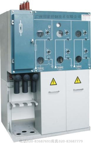
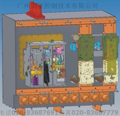
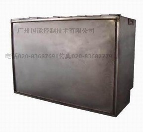
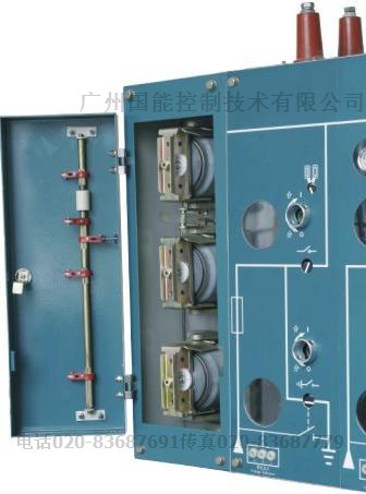
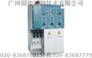
结合我公司多年产品开发和制造经验,自主开发的具有高可靠性的免维护小型化开关柜,产品适用于三相交流50Hz,电压为3-24-35KV/38kV环网供电或辐射供电系统;产品所有高压带电部件,包括负荷开关,断路器,接地开关,一次母线等均密封在充有SF6气体的不锈钢箱体中,进出线采用全密封的肘形电缆插头,受环境影响少,在使用环境比较恶劣及空间比较窄的场所更显出优越性:如:预装式变电站,地下变电站,区矿企业或环境潮湿,污秽较严重的地区.
还有适合铁路专用的27.5kV的C-GIS零表压SF6全绝缘全密封充气柜断路器柜
GB/T11022-1999<<高压开关设备和控制设备标准的共用技术要求>>,
GB3804-2004<3.6KV-40.5KV高压交流负荷开关>>,
GB16926-1997<<高压交流负荷开关-熔断器>>
GB-1985-2004<<高压交流隔离开关和接地开关>>,
DL/T404-1997 <<户内交流高压开关柜订货技术条件>>,
DL/T791-2001<<户内交流充气式开关柜选用导则>>等标准,
在正常条件下运行寿命超过20年.
General
NK(XGN口-12/24/35kV/38kV) series fixed type indoor AC metal clad switchgear (SF6 RMU Abbreviation). one of minimized switchgear with the character of excellence reliability and maintenance free ,is a new product self –developed by R&D of group based on the years experience in R&D and fabrication on products and on the advance technology of ABB SF6 LBS &ABB Uniswitch Safe-Ring\Safe-Plus.
The product is suitable for AC 3 to 24 / 35KV 38kVpower distribution system with configuration either ring
or radiant.. Its all live part including LBS,CB, ES and primary busbar are sealed in the tank made of
stainless steel and the elbow –shape cable connectors and adopted for the incoming or out-going, that
leds it is suitable for use in the bad ambient condition and relatively restricted space ,just like in
pre-fabricated substation, underground substation, industrial and mining enterprises or in high humidity
and heavy pollution area.
The series of RMU is compliance with the following standards and its service life is mord than 20 years under normal ambient condition.
27.5kV Fully insulated sealed inflatable cabinet breaker C-GIS zero gauge SF6
Special for High Speed railway (CRH) Electric System
GB/T1022-1999 <<Common specifications for high-voltage switchgear and controlgear standars>>
IEC 694:1996 Common specifications for high-voltage switchgear and controlgear standards EQV
GB3804-2004 <<Alternating current high voltage load-breaker>>
(IEC 60265-1/FDIS: 1997 high voltage switchgear part 1:Swiches for rated voltage above 1KV and less than 52KV .MOD
GB/T1984-2003 <<Alternating current high –voltage circuit-breaker>>
(IEC 62271-100: 2001 high –voltage switchgear and controlgear part 100: high-voltage alternating-current circuit-breakers .MOD)
GB/T1984-2004<<High-voltage alternating-current disconnectors and earthing Switches>>
(IEC 62271-100: 2002 high –voltage alternating-current disconnectors and earthing switches .MOD)
DL/T404-1997<<Indoor AC high voltage switchgear>>
(IEC298:1990 A.C metal-enclosed switchgear and controlgear for rated voltages above 1KV and up to including 52KV .EQV)
DL/.T791-2001<<Specifications of A.C. HV gas-filled switchgear panel >>
(IEC420:1990 high-voltage alternating current switch-fuse combination and IEC 517-1990
Gas-insulated metal-enclosed switchgear for rated voltage of 72.5KV and above :MOD)
Product code of manufacturer
NK(XGN口-12/24/35)口
NK产品企业代号
X箱型 Cubicle Type
G固定式 Fixde Type
N户内 Indoor
口设计序号 Design Series
12/24/35额定电压kV Rated Voltage
口组合方案(V、F、C、D)
Combination Scheme
V: 真空断路器单元
V: VCB unit
F: 负荷开关熔断器组合单元
F : LBS-Fuse combination unit
C: 负荷开关单元
C: LBS unit
D: 直接进出线单元
D: in & Out Directly unit
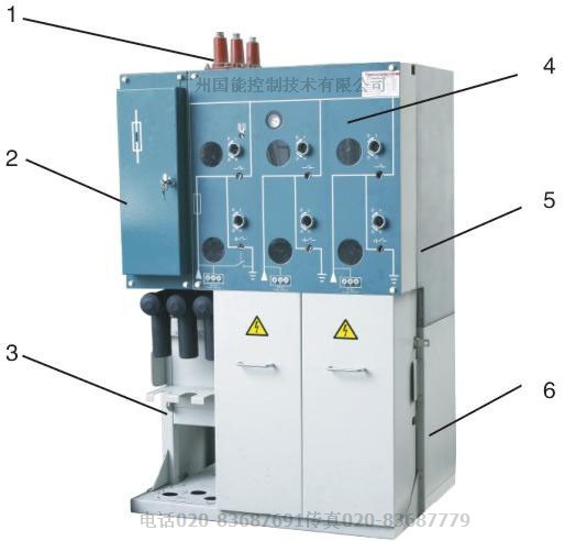
1双通套管(单元扩展用)
2熔断器室
3电缆室
4操作机构
5充气单元
6底架
The outline and base structure of cubicle
1 Connecting bushing(for extending)
2 Fuse chamber
3 Cable chamber
4 Operating mechanism
5 Unit gas filled
6 Support frame
结构特点
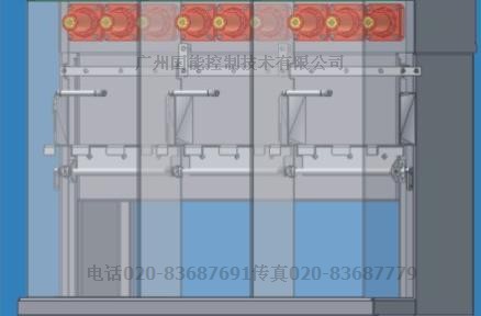
产品由充气室,操作机构,箱体底架,电缆室,熔断器室及低压室等五部分组成:
1共箱式设计:多回路的一次元件安装在同一个充气室内,完成多项供配电功能,组合灵活.
2采用SF6气体作为绝缘介质,最大限度缩小了柜体的体积.
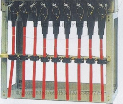
3采用屏蔽型电缆接头,绝缘表面接地可触摸,安全可靠,能适应恶劣的环境条件.
4采用压气式灭弧原理,SF6气体作为灭弧介质,额定转移电流达到2200A
5断路器采用真空灭弧,短路开断能力强,不会污染SF6气体
7充气室设有多个观察窗口,可从多个角度看到断口状态.
8开关柜设有带电显示器,气压表,压力释放装置等,操作安全可靠
9充气室为不锈钢壳体,可靠接地,增加了电气安全性
10负荷开关安装在封闭的绝缘筒中,既减少了污染,又方便更换
11根据用户的需要,在柜体上方可以引出套管作为扩展单元用
12底架空间宽阔,可安装多分支电缆插头及避雷器等
12kV 单间隔柜体尺寸 宽325mm 深751mm高 1336mm
24kV 单间隔柜体尺寸 宽500mm 深751mm高 1336mm
35kV /T630A/T1250A单间隔柜体尺寸 宽600mm 深1030mm高 1800mm
35kV /T2500A单间隔柜体尺寸 宽800mm 深2100mm高 2650mm
备注 顶部/左侧/右侧增加PT,电缆接头,仪表箱,按需要增加尺寸,24kV/35kV地基图及安装图要根据合同图纸来设计
Features in configuration
The RMU consists of 5 portions :Gas filled chamber, Operation mechanism, Supporting frame,Cable chamber, Fuse chamber and Secondary circuit(LV) chamber
1 One tank design: Multi-circuit in one gas filled tank with agile combination to performance difference power distribution functions
2 With SF6 gas as insulated medium to reduce the volume greatly
3 Shield cable terminals with touchable surface and reliable safety character are suitable for abominable ambient condition
4 Using SF6 as the arc extinguishing medium ,the LBS which adopting gas-pressed are extinguishing principle is able to break the transfer current up to 2200A
5 The circuit breaker is vacuum type with high breaking capacity and no pollution to SF6 gas
6 There is a perfect mechanical interlock between LBS and ES.
7 The state of contacts can be chock in difference angles by eye easy from some viewing windows of tank filled
8 The cubicle is equipped with the living indicator, pressure gage and the over pressure releaser to ensure the safety of service
9 The tank filled with gas and made from stainless steel is earthing reliably to increase the electric safety
10 The fuse is barreled in insulated cylinder to prevent the pollution in which the fuse body is easy to replace
11 If need to extend to fit a bushing on the top of cubicle for extending is available
12 The multi-branch cable plugs and arresters can be fitted in bottom support chamber with vast space
|
序号
RF
|
环网柜主要技术参数
名称 Parameter
|
单位
Unit
|
参数Value
|
|
|
|
|
C mod
|
F mod
|
Vmod
|
D mod
|
|
1
|
额定电压 Rated voltage
|
KV
|
12
|
|
2
|
额定
绝缘水平
Rated insulating level
|
工频耐压(1min)
Power
frequency withstand voltage(1min.)
|
相间,相对地
Between phase,phase to earth
|
KV
|
42
|
42
|
42
|
42
|
|
3
|
|
|
断口Across the opened break
|
KV
|
48
|
48
|
48
|
48
|
|
4
|
|
雷电冲击耐压
(峰值)
lightning withstand voltage(peak)
|
相间,相对地
Between phase,phase to earth
|
KV
|
75
|
75
|
75
|
75
|
|
5
|
|
|
断口
Across the opened break
|
KV
|
85
|
85
|
85
|
85
|
|
6
|
额定频率 Rated frequency
|
Hz
|
50
|
|
7
|
额定电流 Rated current
|
A
|
630
|
100
|
630
|
630
|
|
8
|
额定转移电流 Rated transfer current
|
A
|
|
1500
|
|
|
|
9
|
额定短路开断电流 Rated short circuit breaking current
|
KA
|
|
20
|
20
|
|
|
10
|
额定短路关合电流 Rated making current
|
KA
|
50
|
50
|
50
|
|
|
11
|
额定短时耐受电流(负荷/接地开关)
Rated shortime withstand current (LBS/ES)
|
KA
|
20
|
|
20
|
20
|
|
12
|
额定短路持续时间(负荷/接地开关)
Rated short circuit duration (LBS/ES)
|
s
|
3
|
|
3
|
3
|
|
13
|
额定峰值耐受电流(负荷/接地开关)
Rated peak withstand current(LBS/ES)
|
KA
|
50
|
|
50
|
50
|
|
14
|
额定短路关合电流 (接地开关)Rated making current(ES)
|
KA
|
50
|
|
|
15
|
额定机械寿命(负荷开关)Rated mechanincal life(LBS)
|
次times
|
1000
|
1000 (VCB)
(断路器)
|
|
16
|
额定机械寿命(接地开关)Rated mechanincal life(ES)
|
次times
|
1000
|
|
|
17
|
额定
开断电流
Rated breaking current
|
闭环开断电流Breaking current of close loop
|
A
|
630
|
|
|
|
|
|
|
有功负载开断电流
Breaking current of active power
|
A
|
630
|
|
|
|
|
|
|
电缆充电开断电流
Breaking current of cable charging
|
A
|
40
|
|
|
|
|
18
|
撞击脱扣 Strike trip
|
次times
|
|
100
|
|
|
|
19
|
二次回路1min工频耐压
Power frequency withstand voltage on secondary circuit(1 min.)
|
KV
|
2
|
|
21
|
负荷开关短路关合电流操作循环次数
Operation cycle times for short circuit making current of LBS
|
次
times
|
3(E2级) 3(E2 class)
|
|
22
|
SF6气体额定压力(20℃表压)
Rated pressure of SF6 gas (at 20℃,gauge)
|
Mpa
|
0.03
|
|
23
|
柜体及外壳防护等级
Protetcion class of cubicle body and the shell
|
|
IP3X
|
|
|
密封气室防护等级Protetcion class of gas sealing chamber
|
|
IP67
|
|
序号
RF
|
环网柜主要技术参数
名称 Parameter
|
单位
Unit
|
参数Value
|
|
|
|
|
C mod
|
F mod
|
Vmod
|
D mod
|
|
1
|
额定电压 Rated voltage
|
KV
|
24
|
|
2
|
额定
绝缘水平
Rated insulating level
|
工频耐压(1min)
Power
frequency withstand voltage(1min.)
|
相间,相对地
Between phase,phase to earth
|
KV
|
64
|
64
|
64
|
64
|
|
3
|
|
|
断口Across the opened break
|
KV
|
79
|
79
|
79
|
79
|
|
4
|
|
雷电冲击耐压
(峰值)
lightning withstand voltage(peak)
|
相间,相对地
Between phase,phase to earth
|
KV
|
125
|
125
|
125
|
125
|
|
5
|
|
|
断口
Across the opened break
|
KV
|
145
|
145
|
145
|
145
|
|
6
|
额定频率 Rated frequency
|
Hz
|
50
|
|
7
|
额定电流 Rated current
|
A
|
630
|
100
|
630
|
630
|
|
8
|
额定转移电流 Rated transfer current
|
A
|
|
1500
|
|
|
|
9
|
额定短路开断电流 Rated short circuit breaking current
|
KA
|
|
20
|
20
|
|
|
10
|
额定短路关合电流 Rated making current
|
KA
|
50
|
50
|
50
|
|
|
11
|
额定短时耐受电流(负荷/接地开关)
Rated shortime withstand current (LBS/ES)
|
KA
|
20
|
|
20
|
20
|
|
12
|
额定短路持续时间(负荷/接地开关)
Rated short circuit duration (LBS/ES)
|
s
|
3
|
|
3
|
3
|
|
13
|
额定峰值耐受电流(负荷/接地开关)
Rated peak withstand current(LBS/ES)
|
KA
|
50
|
|
50
|
50
|
|
14
|
额定短路关合电流 (接地开关)Rated making current(ES)
|
KA
|
50
|
|
|
15
|
额定机械寿命(负荷开关)Rated mechanincal life(LBS)
|
次times
|
1000
|
1000 (VCB)
(断路器)
|
|
16
|
额定机械寿命(接地开关)Rated mechanincal life(ES)
|
次times
|
1000
|
|
|
17
|
额定
开断电流
Rated breaking current
|
闭环开断电流Breaking current of close loop
|
A
|
630
|
|
|
|
|
|
|
有功负载开断电流
Breaking current of active power
|
A
|
630
|
|
|
|
|
|
|
电缆充电开断电流
Breaking current of cable charging
|
A
|
40
|
|
|
|
|
18
|
撞击脱扣 Strike trip
|
次times
|
|
100
|
|
|
|
19
|
二次回路1min工频耐压
Power frequency withstand voltage on secondary circuit(1 min.)
|
KV
|
2
|
|
21
|
负荷开关短路关合电流操作循环次数
Operation cycle times for short circuit making current of LBS
|
次
times
|
3(E2级) 3(E2 class)
|
|
22
|
SF6气体额定压力(20℃表压)
Rated pressure of SF6 gas (at 20℃,gauge)
|
Mpa
|
0.03
|
|
23
|
柜体及外壳防护等级
Protetcion class of cubicle body and the shell
|
|
IP3X
|
|
|
密封气室防护等级Protetcion class of gas sealing chamber
|
|
IP67
|
|
序号
RF
|
环网柜主要技术参数
名称 Parameter
|
单位
Unit
|
参数Value
|
|
|
|
|
C mod
|
F mod
|
Vmod
|
D mod
|
|
1
|
额定电压 Rated voltage
|
KV
|
35
|
|
2
|
额定
绝缘水平
Rated insulating level
|
工频耐压(1min)
Power
frequency withstand voltage(1min.)
|
相间,相对地
Between phase,phase to earth
|
KV
|
95
|
95
|
95
|
95
|
|
3
|
|
|
断口Across the opened break
|
KV
|
110
|
110
|
110
|
110
|
|
4
|
|
雷电冲击耐压
(峰值)
lightning withstand voltage(peak)
|
相间,相对地
Between phase,phase to earth
|
KV
|
185
|
185
|
185
|
185
|
|
5
|
|
|
断口
Across the opened break
|
KV
|
215
|
215
|
215
|
215
|
|
6
|
额定频率 Rated frequency
|
Hz
|
50
|
|
7
|
额定电流 Rated current
|
A
|
630
|
100
|
630
|
630
|
|
8
|
额定转移电流 Rated transfer current
|
A
|
|
1500
|
|
|
|
9
|
额定短路开断电流 Rated short circuit breaking current
|
KA
|
|
20
|
20
|
|
|
10
|
额定短路关合电流 Rated making current
|
KA
|
50
|
50
|
50
|
|
|
11
|
额定短时耐受电流(负荷/接地开关)
Rated shortime withstand current (LBS/ES)
|
KA
|
20
|
|
20
|
20
|
|
12
|
额定短路持续时间(负荷/接地开关)
Rated short circuit duration (LBS/ES)
|
s
|
3
|
|
3
|
3
|
|
13
|
额定峰值耐受电流(负荷/接地开关)
Rated peak withstand current(LBS/ES)
|
KA
|
50
|
|
50
|
50
|
|
14
|
额定短路关合电流 (接地开关)Rated making current(ES)
|
KA
|
50
|
|
|
15
|
额定机械寿命(负荷开关)Rated mechanincal life(LBS)
|
次times
|
1000
|
1000 (VCB)
(断路器)
|
|
16
|
额定机械寿命(接地开关)Rated mechanincal life(ES)
|
次times
|
1000
|
|
|
17
|
额定
开断电流
Rated breaking current
|
闭环开断电流Breaking current of close loop
|
A
|
630
|
|
|
|
|
|
|
有功负载开断电流
Breaking current of active power
|
A
|
630
|
|
|
|
|
|
|
电缆充电开断电流
Breaking current of cable charging
|
A
|
40
|
|
|
|
|
18
|
撞击脱扣 Strike trip
|
次times
|
|
100
|
|
|
|
19
|
二次回路1min工频耐压
Power frequency withstand voltage on secondary circuit(1 min.)
|
KV
|
2
|
|
21
|
负荷开关短路关合电流操作循环次数
Operation cycle times for short circuit making current of LBS
|
次
times
|
3(E2级) 3(E2 class)
|
|
22
|
SF6气体额定压力(20℃表压)
Rated pressure of SF6 gas (at 20℃,gauge)
|
Mpa
|
0.03
|
|
23
|
柜体及外壳防护等级
Protetcion class of cubicle body and the shell
|
|
IP3X
|
|
|
密封气室防护等级Protetcion class of gas sealing chamber
|
|
IP67
|
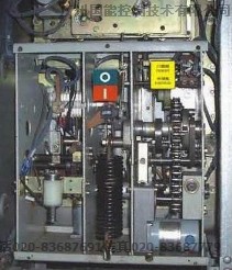
操动机构
手动或电动,弹簧储能快合快分操作.
Operating mechanism
Operating mechanism of LBS: Manual or motor,
Spring energy storing for performing fast C & fast O operation.
手动分合闸操作;合闸时快速合闸装置使主地刀具有关合短路
电流的能力.
Operating mechanism of ES:
Manual operating; The main earthing blade is provided with the capacity of making short circult current due its fast closing design.
There is a rellable mechanical interlock between the LBS and the ES,when the LBS is in close position the ES cannot be closed;when,contrarily,the ES is closed the LBS can not be closed.
手动或电动操作使合闸,分闸弹簧同时储能,操作机构储能后显示”弹簧已储能”..合闸时,合闸弹簧释能快速合闸,分闸弹簧维持储能状态;若有故障电流使熔断器熔断,则熔断器的撞针使脱扣器动作开关快速断开.分闸时,通过手动或电动方式反方向操作(或通过分励脱扣器,熔断器撞击装置动作)使分闸弹簧脱扣后迅速释放以实现”快分”.
The mechanism of LBS-Fuse combination unit:
Manual or motor energize the O & C springs synchronously, The indicator of “ Spring energized “will appear after spring energized.
When closing ,the C spring release the energy stored quickly to close the LBS, the O spring keeps in energized estate, if the fuse is melted due to the fault current, then the firing-pin of fuse strikes the releaser of LBS to open quickly.
When opening, the O spring will release the stored energy to perform the “ast open” by the opposition-operation of manual or motor (or by the shunt releaser or by the strike action of the firing-pin of fuse)
断路器操动机构
采用弹簧操作机构,通过波纹管密封装置传递分合闸动力.
Operating mechanism of CB
Spring mechanism drives the close or open energy to CB by seal bellows driver
充气室
SF6环网柜是一种小型的GIS开关设备,所有高压带电部件均封闭在不锈钢壳体内,箱体里充有相对压力为0.03Mpa的SF6气体,起绝缘及灭弧作用.
充气室内安装有专用的吸附剂,可有效控制SF6气体的水分含量以及电弧分解物所产生的其他杂质.
每个充气室带有气压表,底部装有压力释放装置和释放通道,当箱体内部气压由于短路故障,高温等原因导致异常升高时,它首先被破而释放压力,对人身及设备起到了安全防护作用.
Gas filled chamber
NK(XGN口-12/24/35kV)series SF6 RMU is a kind of GIS ,its all HV living part are sealed in a stainless
Steel tank which filled with SF6 gas at 0.03Mpa in as insulation and arc extinguishing medium.
There is a special absorbent inside ,to absorb the trace moisture of SF6 gas and the decompositions of SF6 by the function of arc and other impurity/.
Each gas-filled tank of cubicle is equipped with a pressure gauge, and with a pressure releaser and the pressure relief channel. If the gas pressure in the tank rises up to abnormal value due to the arc or high temperature ,then the releaser is broken firstly by pressure to release the pressure therefore to ensure the
Safety of operator and the equipment.
负荷开关以SF6气体作为绝缘和灭弧介质,采用独特的直动压气式灭弧原理.利用活塞和气缸在开断过程中的相对运动产生压缩气体经喷口处高速吹向电弧,电弧被拉长,并冷却至熄灭
LBS
The LBS adopts the princlple of straight move to compress gas to extinguish the arc.The current carrying part is apart from the arc-extinguishing prat,during the opening, the gas compressed by the piston
and cylinder with opposite movement blows to the arc quickly via a nozzle,then the arc is being stretched
and cooled off till quenched
熔断器安装在环氧树脂制成的绝缘套筒中,从柜前可以很容易的进行更换.绝缘套筒插入到充气室内,并与充气室之间有很好的密土封,既保证了充气室内SF6气体不会泄漏,又保证了充气室内电气部件与熔断器之间可靠的电气连接.任意一相熔断器熔断,负荷开关脱扣跳闸.
LBS-Fuse combination unit
The fuse is barreled in insulated cylinder in which the fuse body is easy to replace from the
Front side of cubicle. The insulated cylinder is inserted in gas filled tank and with sealed well from
Tank ,so the gas in the tank can not leak and the fuse has a reliable contact with the living part in side.
If the fuse in any phase is melted due to the fault current, then LBS to be opened quickly.
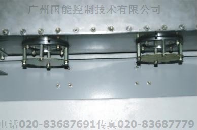
电缆的安装与连接
位于柜体下部的电缆室,实现多回路的进出线连接
Cable connection:
Multi-circuit cables can be arranged and connected in the nether cable chamber.
单元扩展:
位于柜体上部引出的双通套管,通过绝缘母线实现与相邻柜体的自由组合及扩展
Unit extending :
The bushing located in the top of cubicle can be used for joining the contiguous cubicles freely and extending by insulated busbar ducts
多于5回路时采用绝缘母线扩展
Insulated busbar ducts are suitably used for extending the circuits as that is more than 5
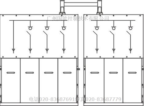
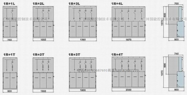
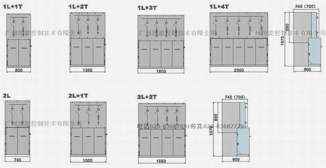
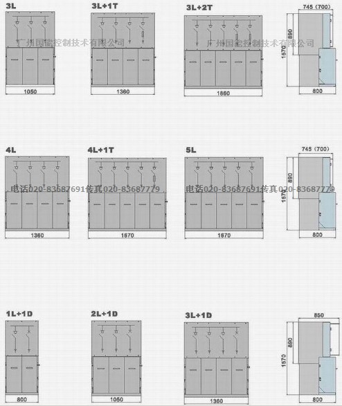
环网柜主要方案(可根据用户要求进行左侧扩展,右侧扩展,左右两侧扩展;左侧进出线,右侧进出线.)
The main scheme of the RMU
(The extending of cubicle in double side or in one side is available according to the requirement of
user, the side in-coming or out-going arrangement is also available.)
12kV 单间隔柜体尺寸 宽325mm 深751mm高 1336mm
24kV 单间隔柜体尺寸 宽500mm 深751mm高 1336mm
35kV /T630A/T1250A单间隔柜体尺寸 宽600mm 深1030mm高 1800mm
35kV /T2500A单间隔柜体尺寸 宽800mm 深2100mm高 2650mm
备注 顶部/左侧/右侧增加PT,电缆接头,仪表箱,按需要增加尺寸,24kV/35kV地基图及安装图要根据合同图纸来设计
注: R-直接进线单元 L-负荷开关单元 T-负荷开关熔断器组合单元 D-真空断路器单元
带有熔断器方案柜体上方深度为745mm, 只有负荷开关方案柜体上方深度为700mm
带断路器方案柜体上方深度为850mm
Note: D=745mm for with fuse
D=700mm for with LBS only
D=850mm for with VCB
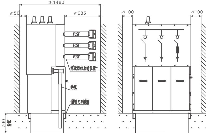
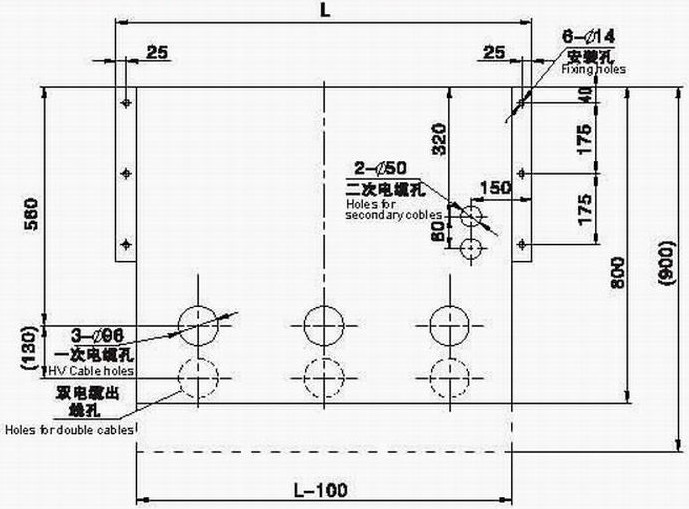
安装
.开关设备安装基础的施工应符合<<电力建设施工及验收技术规范>>中的有关条款规定:
电房高度不低于2.5米
柜体单列时,柜前走廊以1.5米为宜;双列布置时,柜间操作走廊以2米为宜;
一次电缆终端安装严格按相关工艺要求:
电缆沟上方预埋10号槽钢,柜子放在槽钢上固定;
Installation
The foundation for cubicle should be in conformance with the relative requirements Stipulated in
<<The Code of Erection and Acceptance of Electric Power Construction>>
The height of cubicle room should not be lower than 2.5m
The width of the corridor in front of cubicles which are arranged in one row takes 1.5m properly,2m for
Double rows arrangement
The assembly of primary cable terminals should be in accordance with requirements of relative technology
Strictly
The No.10 U type steel should be built in the top edges of cable trench as the base of cubicle
订货时需确定的资料内容
一次线路系统图,排列图及平面布置图
二次线路原理图,其中包括操作,信号,保护回路各电器无件的型号规格
开关柜内电器元件的型号,规格,数量
特殊环境条件下的要求
附件及备件的种类和数量
用户需要的特殊要求,订货时可以与制造厂协商
The information specified for ordering
Primary scheme and the layout or arrangement sketch
Principle diagram of secondary circuit, including the type and the spec of electric components in operation,
Signal and protection circuit
The type, specification and quantity of primary components in the cubicle
Special ambient condition
The sorts and the quantity of accessories and spare parts
For special requirement, if any, please contact the manufacturer
公司在各地有常驻办事处,随时随地为你服务,并提供及时完善的售后服务,我公司分界开关己广泛应用到山东潍坊聊城广西南宁河池宁夏并逐步扩展到上海江苏南京苏州昆山太仓吴江无锡宜兴常州扬州泰州镇江南通浙江湖州杭州红外检测服务红宁波慈溪绍兴嵊州金华义乌红外检测服务温州台州丽水舟山衢州,北京天津河北保定唐山沧州承德张家口秦皇岛石家庄邢台,内蒙古海南海口云南昆明贵州贵阳,福建福州厦门山东济南青岛,湖南长沙株洲深圳东莞广州韶关珠海汕头佛山江门湛江茂名肇庆惠州梅州汕尾河源阳江清远东莞中山潮州揭阳云浮深圳红外检测赤湾盐田广州宁波镇海慈溪舟山上海宝山外高桥洋山山东青岛济南福建厦门浙江杭州等电力,供电,发电,电信,石化,钢铁,烟草,,建筑业等各大企业
主要销主要销售范围:
广西 广东 宁夏 山东 浙江 上海 天津 辽宁 云南 安徽 北京 新疆 重庆 湖南 湖北 河北 河南 青海甘肃 陕西 西藏 贵州 四川 海南 黑龙江 内蒙古 福建 吉林 山西 江西 江苏
产品销售全国各地
广东省:广州市深圳市江门市佛山市汕头市湛江市韶关市中山市珠海市茂名市肇庆市阳江市惠州市潮州市揭阳市清远市河源市东莞市汕尾市云浮市
广西省自治区:南宁市贺州市柳州市桂林市梧州市北海市玉林市钦州市百色市防城港贵港市河池市崇左市来宾市
山东省:潍坊市淄博市威海市枣庄市泰安市临沂市东营市济宁市烟台市菏泽市日照市德州市聊城市滨州市莱芜市
宁夏:银川市固原市青铜峡市石嘴山市中卫市
新疆:乌鲁木齐克拉玛依市伊宁 喀什 奎屯 石河子 哈密 库尔勒 昌吉 阿克苏 和田
河北省:石家庄保定市秦皇岛唐山市邯郸市邢台市沧州市承德市廊坊市衡水市张家口
山西省:太原市大同市阳泉市长治市临汾市晋中市运城市晋城市忻州市朔州市吕梁市
内蒙古:呼和浩特呼伦贝尔包头市赤峰市乌海市通辽市鄂尔多斯乌兰察布巴彦淖尔
辽宁省:盘锦市鞍山市抚顺市本溪市铁岭市锦州市丹东市辽阳市葫芦岛阜新市朝阳市营口市
吉林省:吉林市通化市白城市四平市辽源市松原市白山市
黑龙江省:哈尔滨市伊春市牡丹江大庆市鸡西市鹤岗市绥化市双鸭山七台河佳木斯黑河市齐齐哈尔市
江苏省:南京市无锡市常州市扬州市徐州市苏州市连云港盐城市淮安市宿迁市镇江市南通市泰州市
浙江省:杭州市绍兴市温州市湖州市嘉兴市台州市金华市舟山市衢州市丽水市
安徽省: 合肥市芜湖市亳州市马鞍山池州市淮南市淮北市蚌埠市巢湖市安庆市宿州市宣城市滁州市黄山市六安市阜阳市铜陵市
福建省:福州市厦门市泉州市漳州市南平市三明市龙岩市莆田市宁德市
江西省:南昌市赣州市景德镇九江市萍乡市新余市抚州市宜春市上饶市鹰潭市吉安市
河南省:郑州市洛阳市焦作市商丘市信阳市新乡市安阳市开封市漯河市南阳市鹤壁市平顶山濮阳市许昌市周口市三门峡驻马店
湖北省:武汉市荆门市咸宁市襄樊市荆州市黄石市宜昌市随州市鄂州市孝感市黄冈市十堰市
湖南省:长沙市郴州市娄底市衡阳市株洲市湘潭市岳阳市常德市邵阳市益阳市永州市张家界怀化市
海南省:海口市三亚市
四川省:乐山市雅安市广安市南充市自贡市泸州市内江市宜宾市广元市达州市资阳市绵阳市眉山市巴中市攀枝花遂宁市德阳市
贵州省:贵阳市安顺市遵义市六盘水
云南省:昆明市玉溪市大理市曲靖市昭通市保山市丽江市临沧市
西藏:拉萨市阿里
陕西省:西安市咸阳市榆林市宝鸡市铜川市渭南市汉中市安康市商洛市延安市
甘肃省:兰州市白银市武威市金昌市平凉市张掖市嘉峪关酒泉市庆阳市定西市陇南市天水市
青海省:西宁市
.